With the help of advanced analysis software, microclimate simulation studies are having an increased impact on the design process. Toby Sargant, Nicholas Waterson and Iain Bowman from consultancy Mott MacDonald discuss how this opens up opportunities for engineers, architects and developers to work together to create more appropriate local environments.
English physicist and natural philosopher Sir Isaac NewtonÝs third law of motion states that Ùto every action there is an equal and opposite reactionÝ. Together with the first two laws, which cover inertia and acceleration, this forms the basis of classical mechanics and has guided the understanding of the physical world as we know it.
NewtonÝs laws of motion may seem incongruous in a discussion about climate simulation, but in fact there are important parallels. The third law means that all forces are interactions ¾ that there is no such thing as a force without a reaction. So, the height, shape, material and position of a new building or structure will have an effect on the environment around it. Tweak any one of those and the effect will change.
The effect of different building influences on the environment is being examined as never before by Computer Aided Engineering (CAE). Powered by the increase in computing power, and more sophisticated software, CAE now offers untold possibilities for many projects in the built environment.
Computational fluid dynamics (CFD), for example, can offer detailed calculations of air flows both in and around complex structures and large spaces such as atria and stadia. Powerful visualisation techniques can be used to extract extra physical insights from the complex mathematical analyses for simple illustrations to the lay person.
At the same time, traditional hand calculations for assessing daylight effects are being replaced increasingly by computer simulation techniques, which are able to handle a large volume of calculations and produce colourful and accessible graphical outputs. This allows technical consultants to provide clear and concise findings to clients and planning authorities alike. The calculations involved in microclimatic studies are by their nature technical and can be misinterpreted or misunderstood without adequate presentation.
The rise in use of CAE produces some cause for thought. Successful application of CAE is not simply about computational power. Now, more than ever, it requires specialist expertise to ensure that simulations are run with careful thought regarding their purpose, as well as ensuring the accurate building of models and the appropriate representation of the physics of the problem. Such CAE analyses require the same level of preparation and clear conclusions and advice as any other complex calculations.
Winds of change
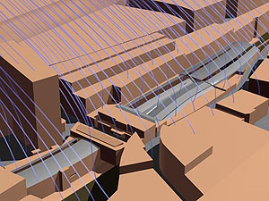
While the use of CFD techniques to predict wind loads on buildings remains problematic and controversial, their application to wind flow around groups of buildings to ascertain their effect on the ground-level wind environment is becoming increasingly well established. Analyses usually attempt to predict mean velocities close to ground level, which can then be used to assess the situation with regard to one of various sets of criteria.
The most famous classification of wind speeds is the Beaufort scale, developed originally for use at sea but which can be converted for use on land. Modern wind-comfort criteria usually include some combination of the following aspects:
- Wind speed (mean and gust);
- Frequency of occurrence;
- Activity talking place e.g. sitting in open cafes versus Ùbusiness walkingÝ. Different speeds will be acceptable dependent upon frequency and type of activity taking place. It is recognised that gusting can affect wind comfort (in addition to the basic mean wind speed), though this aspect is difficult to reproduce meaningfully in a typical Reynolds-averaged flow simulation.
The increased availability over the last decade of CFD codes, such as Ansys CFX, able to give solutions on hybrid meshes of tetrahedra, hexahedra, prisms and pyramids has greatly reduced the cost of undertaking such studies and enabled them to be used at the early stages of the design process where they can have greatest impact. Creating meaningful solutions still, however, requires care and expertise, in particular in specifying a representative atmospheric boundary layer.
Wind flow simulations have a number of other applications including:
- Wind-driven rain assessment;
- Effect of sea spray;
- Ventilation inlet/outlet positioning;
- Natural ventilation design;
- Stadium pitch ventilation;
- Pollutant and dust dispersion.
As mentioned above, the obvious application to the prediction of wind loading on buildings remains largely the domain of physical wind-tunnel simulations due to the continuing technical challenges involved.
In the spotlight
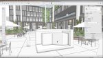
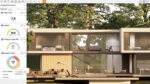
Natural lighting calculations for buildings used to be undertaken with a variety of methods, from shining lights onto scale models to producing hand-drawn Waldram diagrams and counting shaded squares. CAE tools, such as Ecotect, can now do much of this ± assessing lighting characteristics of a development using recognised indices, considering both the internal characteristics of the development and the impact on the surrounding environment.
This enables designers to optimise the natural characteristics of a design. In an age of environmental awareness, this ensures the best use of natural lighting and minimises the need for artificial lighting, producing both cost and environmental savings. Often of more interest to developers, the impact of a design on the surrounding environment and neighbouring properties can be assessed and addressed, thus minimising the risk of possible litigation against them.
The Building Research Establishment (BRE) in the United Kingdom recommends the use of two specific metrics that assess the potential for good lighting afforded by windows for both direct and indirect light, namely the Vertical Sky Component (VSC) and the Annual Probable Sunlight Hours (APSH).
Alongside consideration of the buildings within a development, the shading of open spaces is also calculated. These parameters are seen as indicators and design tools, to inform the design, rather than rigid regulations that must be adhered to. If concerns are apparent in areas of the development then further investigations into Lux levels and Average Daylight Factors can be undertaken. Here we focus on the initial calculations of VSC and APSH, but similar CAE tools and methods can be used to calculate other lighting characteristics for a new development.
SkyÝs the limit
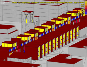
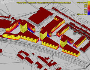
The Vertical Sky Component is a measure of a wall or windowÝs access to daylight, with daylight referring to indirect or diffuse light received from the sky. A high VSC would afford a room a generally bright appearance, while a low VSC would imply a gloomy feel. In simple terms, the VSC is a measurement of the percentage of the sky that can be seen from a vertical face of a building. When looking out of a window only 50 percent of the sky would be visible when uninterrupted by buildings. Taking into account that not all light in the sky is of equal importance, the sky model is distorted to give a maximum possible VSC value of 40 percent.
{mospagebreak}
When considering the effect of developments on daylight for residential buildings, the BRE guidelines suggest that non-reception rooms such as bathrooms, toilets, storerooms, circulation areas and garages need not be analysed, and that bedrooms, while they should be analysed, are less important than other living areas in terms of access to daylight. The BRE guidelines propose that: ýFor a room with non-continuous obstructions there is the potential for good daylight provided that the vertical sky component, at the window position 2m above ground, is not less than the value for a continuous obstruction of altitude 25 degrees. This is equal to a vertical sky component of 27 percent.¯
The Annual Probable Sunlight Hours (APSH) measures the access to direct sunlight, with sunlight referring to light that falls directly from the sun on a fa?ade and is only of interest to those fa?ades facing within 90 degrees of south. By looking at the path of the sun through the sky, calculations can be made showing the percentage of time that a fa?ade will spend in shade.
A high APSH means the room will receive a high amount of direct sunlight. Similarly to the VSC, the BRE Guidelines suggest that sunlight is of importance in living rooms and conservatories, but is less so in bedrooms and kitchens: ýBritish Standard recommends that interiors where the occupants expect sunlight should receive at least one quarter of annual probable sunlight, including at least 5per cent of annual probable sunlight hours during the winter months, between 21 September and 21 March.¯
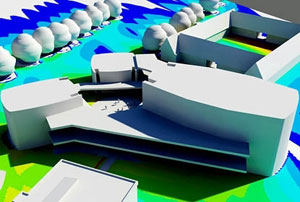
For ground shading, the shadowing cast by the proposed development on the equinox on 21 March is calculated. Only sunlight from above an angle of 10 degrees from the horizon is assessed, in accordance with recommendations in the BRE guidelines: ýIt is suggested that no more than two-fifths, and preferably no more than a quarter, of any of the listed amenity areas should be prevented by buildings from receiving any sunlight at all on 21 March.¯
The method BRE suggests for the calculation of VSC is using Waldram Diagrams. In essence these are a camera ÙprojectionÝ of the view seen by a fa?ade, similar to a fisheye lens. From this the percentage of sky obscured by buildings can be calculated.

A number of modern CAE tools work using similar principles, dividing the ÙskyÝ into blocks and calculating the number any one fa?ade can see.
Whereas the hand-drawn diagrams of the past were costly and time consuming to produce, CAE can undertake the calculations in seconds. With the increase in speed there is also an increase in accuracy ± while traditional techniques may only provide results to the nearest integer, modern CAE tools can provide results to a couple of decimal places. Similarly for direct sunlight, by specifying the location of a development, a sun-path diagram can be calculated for each fa?ade, from which the time spent in shade can be speedily calculated.
Turning wisdom on its head
CAE tools can provide advanced analyses to inform the design process, providing more comprehensive and accurate studies than were previously possible. However, with the emergence of these relatively widely available techniques, and the associated volume of design data for clients and planners to consider, it is the advice produced as a result of the analysis that is more important than the results themselves. The judgements and proposed enhancements of the experienced practitioner, based on the analysis data, can bring real value to a project.
CAE analysis can help to produce improved designs. In simple cases, for example, landscaping can be modified to reduce wind speed and shading to allow a more pleasant environment. In other cases, the usage of areas in poorly lit sections or those with higher wind velocities can be changed. Where designs have serious issues then they may require more serious redesign, maybe producing radical, innovative and unexpected results, literally turning traditional wisdom on its head, such as moving living areas up in houses and bedrooms down.
Extensive redesign can be seen as being in direct conflict with commercial and other considerations. Listed buildings may need to be worked around as may transport and other key local issues. The logic behind some decisions might, however, need to be challenged. One common issue, for example, is that reducing building dimensions or profiles to create more favourable microclimatic conditions can reduce the floor space within developments, which may limit the projectÝs commercial viability. This has to be balanced, however, against the real benefits that can be gained from such a discussion.
Is it more beneficial, and therefore more commercially viable, to have large designs with less favourable microclimatic conditions, or smaller designs with more benign ones? If areas are to be for outdoor use, which is more appealing to a potential investor: sitting in a square that is shaded and windy, or one that is sunny and calm? Developers who push ahead with the former, may find that once built the design is not the attractive proposition it seemed at the outset.
While CAE tools can help by assessing various mitigation measures, they are unlikely to be as successful as modifications made during the original design process.
Hidden within this is the lack of definitively agreed acceptance criteria. The BRE guidelines are just that, guidelines, that can be heeded or not. There is no universal agreement that the criteria that they outline are sensible or worth adhering to. These, and a lot of the right to light analyses, are based on research undertaken in the early 20th century by people like P J and J M Waldram and A K Taylor. Modern lighting tools use variations on their methods but are these methods sufficient?
Similarly for wind microclimate, there is no single set of internationally-accepted criteria and little regulatory specification, beyond an increasing recognition by planning authorities of the importance of wind effects. Even within a single country it is not unusual to find various sets of criteria in use (and indeed multiple sets of criteria referenced to the same author).
Therefore, while CAE can offer useful results, the underpinning techniques and methods of interpreting the results should always be reviewed and questioned.
Conclusions
The spread of CAE has led to better and more informed design, as well as providing planning authorities with material to better inform their decisions in building sustainable and high quality environments. The use of CAE, however, still requires expert knowledge in its application and interpretation. CAE tools in themselves cannot create the best design solutions, it is the guidance given based on their results that is important. With limited consensus on the criteria on which these judgements should be based this can sometimes prove challenging.
It is, however, beyond doubt that strong clear advice produced from CAE techniques can help us to design environments that do not just work aesthetically, but also technically, helping to produce sustainable high quality designs that satisfy the many and varying demands to which they will be subject.
www.ansys.com
simulation@mottmac.com