Survey software provider Kubit, recently acquired by Faro, goes back to basics with its analysis of the implications and ways of surveyed data capture
Building Information Modelling (BIM) methodology is increasingly penetrating into building design. It will also lead to an inevitable increase in the demand for BIM modelling in the existing building stock. That raises the question, what is the most effective method of surveying existing buildings? Laser scanning appears to be the ideal solution. It allows the quick and precise high definition capture of 3D data. Various pilot projects and user reports tell of the effectiveness of the procedure as the basis for creating a 3D BIM model (among others, Fletcher 2013). But, thereby, is the procedure ‘Scan-to-BIM’ by no means trivial. The challenge here is to create a parametric 3D BIM model from the precise depiction of the real world, in the form of a point cloud.
The point cloud as reference model
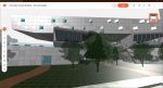
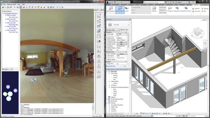
First it is necessary to transfer the original survey data into the required BIM system. Currently there are only a few BIM systems, such as, for example, Autodesk Revit, that are capable of importing and displaying large point clouds. There, it is then possible to use the point cloud as a modelling reference, whereby sections from and planar views of the point cloud can be extracted. Point snapping allows the precise remodelling of the point cloud regions with 3D BIM elements (figure 1).
Besides the spatial display of the whole point cloud it is also additionally possible to use the scan view of the individual scans for modelling.
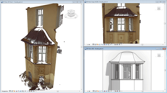
In the scan view all of the surveyed points from a single scanner set up can be displayed in a photo-like panorama view. This high resolution image of the observed situation offers in many cases advantages by way of simple and intuitive navigation over the 3D display of the whole point cloud. In this view each point contains the correct 3D information of the total referenced point cloud (figure 2).
If the target system does not have the necessary point cloud functionality then there remains two alternatives: the creation of 2D intermediate results as modelling references, or the use of the scan view in an external piece of software with an interface to the BIM system.
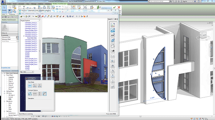
In the first case, in the appropriate software, 2D CAD drawings, or also ortho images as planar projections, of the point cloud are created. These intermediate results can afterwards be attached as references in the BIM system (figure 3).
Disadvantage of this workflow: the valuable information density of the point cloud is reduced to a two-dimensional projection. This loss of information can later be reflected in incorrect 3D modelling.
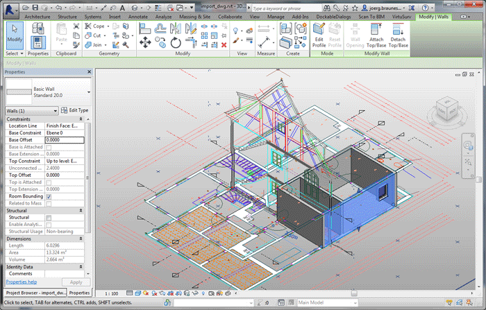
As an alternative to this, the photo-like scan view of the individual scans can be used in an external piece of software for 3D modelling. Using an interface, the 3D co-ordinates in the scan can be obtained and transferred to the BIM system for object creation (figure 4).
Despite the high quality data of the point cloud, this form of modelling remains, to a large extent, a manual and time consuming process that is very cost intensive. Thereby, there is an increasing need for an automated solution to create BIM models from point clouds.
Fully- vs semi-automated recognition
The paramount wish on the software developer is doubtlessly for fully-automatic and flawless pattern recognition. The software should analyse the whole point cloud, locate all of the fittings, recognise their type and fit the position and parameters optimally onto the observed data. An appealing notion, but unfortunately rather unrealistic.
Such a fully automated system requires the acceptance of the closed world assumption, that means that everything that is to be found in the point cloud, must also be able to be modelled in the BIM system, but:
In large point clouds there are always interference objects such as furniture, panelling or house plants. These would be either incorrectly interpreted (they would not be able to be modelled in the BIM system) or they would hinder recognition of the object (e.g. a plant pot on the window sill)
Real objects always have more characteristics than those that are relevant or capable of being modelled. For example for the model of a window only the parameters width, height and sill to floor height should be recognised and modelled. A fully-automated system must, however, recognise all of the characteristics of the window, that is to say, the frame, sashes, glazing bars, ironmongery, etc. to be able to safely recognise the window
Point clouds do not fully describe the geometry. Shadows in the field of view of the scanner create holes. A fully-automated system must understand these holes as such to be able to “invent” any missing object features (e.g. the lower left corner of a window, if a sofa is in front of it)
An implementable solution would offer semi-automatic pattern recognition, where the specific acceptance of the position, size and/or type of the object to be recognised by the system would be predefined by the user.
The function of the system is to minimise the distance between the surface of the object and the point cloud by adjusting the object’s parameters.
The complexity of such an optimisation and the effort involved increases with the number of variable parameters the object possesses.
The solution possibilities for such an optimisation problem for complex bodies are discussed in Bringmann 2010.
Even architectural components possess through their diversity a large number of parameters that results in a very time consuming optimisation process. Good workflows are therefore required, where the amount of user input is reduced to a minimum, but at the same time the object can be recognised quickly and robustly by the software.
Implications of surveyed data capture Current BIM systems have their roots in new build planning, from which certain conventions have resulted in their functionality: Orthogonality of walls, parallel wall surfaces and uniform wall cross sections.
In old buildings there are often divergences from these conventions, such as wall deformations or sagging ceilings. These are only capable of being modelled with a great deal of effort and sometimes it is not at all possible to model the situation. It is therefore necessary to find a compromise between the required accuracy of the model and the conventions of the BIM system.
Generalisations vs accuracy
It is indisputable that the purpose of the building survey determines the amount of detail and the accuracy of the model. For facility management purposes, the visualisation or the simple planning of alterations, certain generalisations are not at all problematic and are in many cases desirable, to simplify or as the case may be to first allow further work in the BIM system.
Built heritage conservation and building research projects or structural stability analyses, however, require a higher degree of accuracy and hence a lower level of generalisation of the model.
It is therefore necessary to enquire as to the purpose of the BIM model when the amount of work involved in creating the model increases significantly in respect to its purpose. It is therefore to be ensured whether the generalisation is necessary or desired, and if the variance between the BIM model and the point cloud remains acceptable.
An optimisation task
With all of the prerequisites of generalisation it naturally begs the question, how the software can work. In Bringmann 2010 and 2012 it is demonstrated that only a global consideration of all of the survey data can be carried out for this task.
figure 5 illustrates this with an example of a floor plan, in which the walls are constrained perpendicular to each other
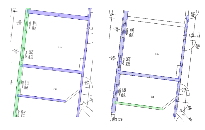
On the other hand if one considers all of the walls in the floor plan, one can recognise two large clusters and a transitional area, in which all walls are perpendicular to each other (figure 6).
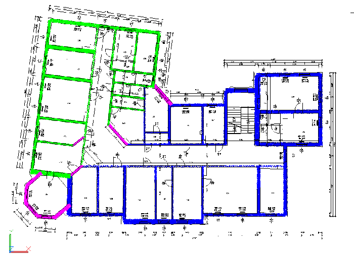
In an optimised BIM model the number of such orthogonal clusters should be as small as possible. Further conditions for an optimised BIM model can be described as:
Minimum number of walls
continuous walls through several rooms
constant wall thicknesses
aligned walls over breaks/extensions
Minimum number of orthogonal clusters
right angles
Minimum number of grid clusters
architectural elements such as walls and columns lie on a grid
“round numbers” for room widths, etc.
The use of structural dimensions instead of the actual measurable surfaces
Wherever possible the use of standard sizes for wall thicknesses
Based on these properties software would carry out the following optimisations tasks: A component model is required which satisfies the predefined properties (where applicable with weightings). The maximum variance must not exceed a given tolerance.
Conclusion
Already today it is not possible to imagine the world of the construction industry without BIM. Sooner or later it will also apply to conversion and renovation projects, so much so that the demand for solutions that can create BIM models from survey data will constantly increase.
Laser scanning promises to be the technology that is best suited for the task of producing, at a commercially viable cost, a precise base of data for modelling in BIM systems. There already exists usable solutions, however in the area of automated modelling there is a great need for optimised workflows. The software industry is working on the task, so that these solutions can be expected on the market in the near future.
If you enjoyed this article, subscribe to AEC Magazine for FREE