In the final part of Darren BrookerÝs four-part comparison of the interior lighting methods available within 3ds Max, he looks at the role of HDR lighting and relighting your scene with both 3ds Max and combustion
Having started this four-part series with the Global Illumination tools available within 3ds MaxÝs scanline renderer before moving onto equivalent photon mapping techniques within mental ray, we then progressed on to the use of standard lights to fake the look of Global Illumination. In this, the last part of this series on lighting in 3ds Max, weÝll take a look at using mental ray again to create High Dynamic Range (HDR) images, which can then be used to light and relight your scene, with the help of combustion.
1. Simple to setup
2. Perfect for match lighting
3. Versatile, especially in a compositing pipeline
Negatives:
1. Generation of HDR maps can be tricky
2. Sampling settings can be difficult to optimise
3. Relatively slow to calculate
Tips & Tricks
- Work with white materials initially to define your render settings
- Introduce curved objects to help define your render settings
- Experiment with Exposure Control settings
- View your images in the viewport background to check alignment
- Work with HDR/OpenEXR formats to retain the full dynamic range
- Render HDR images using mental ray, not the scanline
- Turn your frame buffer from 16-bit to 32-bit floating-point
- Render an ambient occlusion pass to apply as a composite layer
Regular 8-bit RGB images store an 8-bit value for each channel, giving us 256 increments of Red, Green and Blue, which means that all whites are clipped at R:255, G:255, B:255. HDR images, on the other hand, are floating-point images, and are capable of storing a far higher luminance range. When both HDR and 8-bit images are displayed on our 8-bit monitors, we cannot see the difference between the white of a wall and the white of the sun, but internally, when working with HDR images, the renderer sees a luminance value of 300 allocated to the wall, but a luminance value of 10,000 allocated to the sun.
HDR images are generally created using photographs taken at different exposure settings. By exposing correctly for the brightest light in the scene incrementally down to the least bright, all highlights and shadows are captured at a mid-tone exposure level. These photographs are then assembled into a single image using software like HDRshop, as shown in Figure 1 (www.hdrshop.com) and these luminance levels are essentially layered, which gives the brightest highlights the super-whites within the resultant HDR image. Within a film pipeline, it took a relatively long time for HDR images to catch on (the first real application was in 2000Ýs X-Men), but it is now commonplace for chrome spheres to be photographed at multiple exposures on set to enable CG content to be easily lit to match the live action backplate.
Just as spheres can be used to capture a live action environment, HDR output can also be rendered out as spherical images, which essentially does the same thing, capturing what would be reflected if a chrome ball were photographed on set. To calculate floating-point values in the first place requires a floating-point renderer, which is where mental ray comes in.
{mospagebreak}
If you open 04mentalRayHDR.max you will see that the scene is all set up to render. Look in the Indirect Illumination tab of the Render Scene dialog and you will see that the Final Gather map has been pre-calculated. However, rather than render through this dialog, weÝre going to use the Panorama Exporter utility to render a spherical image. See Figure 2.
Within the Utilities panel, hit the MoreÍ button in the top-left corner and choose Panorama Exporter. Hit the RenderÍ button and you will see that the resultant dialog looks rather similar to the Render Scene dialog, but with all the rollouts from the various tabs of this familiar dialog all placed next to one another in one dialog. There are a few subtle differences between these two dialogs though; the first being that there is a field for your cameraÝs Aperture Width in this new dialog, which is not usually in the render dialog.
This has a standard setting of 20.12mm and needs to be changed to match the camera that youÝre using in your scene, so select your cameraRender object from the scene (youÝll unfortunately have to close the new Render dialog first, in order to do this). In the Modify panel, you can see that your camera has a 14.493mm Lens value, which is the equivalent to Aperture Width. Copy this value from this field and go back to the Utility panel, hit RenderÍ again and Paste this value into the Aperture Width field.
This dialog should have picked up the render settings from the Render Scene dialog, so everything should be set up properly. One thing to note is within the Sampling Quality rollout, which contains a drop-down named Frame Buffer type. When set to Floating-Point this returns 32-bit information within the Frame Buffer, which is important for HDR rendering, as weÝll need to render to the Frame Buffer and then save this as a spherical image from this window. Ensure that this is set to Floating-Point and set the Output Size to 2,048×1,024, set the output to the .hdr file type and hit Render.
This will take a reasonably long time to render, as what the Panorama Exporter does is render out six images, one each up and down the cameraÝs local X, Y and Z axes, before stitching them together to form a single rendered image. When this has finished rendering, you should be left with a single image displayed. If you click and drag within this window using the left-hand mouse button, you will see that you can tumble around this image and see how the six images have been stitched together to make this one. The seam is most apparent on the upper-right hand area of the ceiling. This is no problem, however. From this window, you should choose File > Export > Export Sphere and save out this image as another .hdr image.
Now that you have this image, you can render additional geometry to match your original scene, lighting it with this spherical image. To see how this is done, open up the 04mentalRayHDRfinished.max scene file. You should see that there is an additional foreground element in this version of the scene, which is the element that weÝll now render. If you right-click any other object in the scene and choose Object PropertiesÍ youÝll see that this object is set to non-renderable and that your sceneÝs lights are turned off. This is because your HDR map contains all of this information. To use this to light your scene, all you need to do is create a Skylight anywhere in the scene and, once created, hit the Map button for Sky Color and choose Bitmap, then pick the mentalRay.hdr map from your sceneassets\images directory, accepting the defaults from the dialog that appears.
{mospagebreak}
Once youÝve done this, open up the Material Editor and drag this image from the lightÝs modifier panel to a blank slot in the Material Editor, choosing Instance. Now open up the Rendering > Environment dialog box and drag this from the Material Editor to the Environment Map slot, again choosing Instance. Now, with the cameraRender viewport active, hit Alt + B to bring up the Viewport Background dialog. Check both the Use Environment Background and Display Background checkboxes before hitting OK. You should see a crazy pattern appear in the viewport, which youÝll now correct in the Material Editor. Within the bitmapÝs Coordinates rollout, choose the Environ radio button and choose Spherical Environment from the Mapping drop-down, which will give you a solid grey background. You now need to adjust the U and V Offsets to match the image to the background. First set the U Offset to 0.303. You should see that the image is back to front, left to right, so change the U Tiling setting to -1.0, which should match everything left to right. To see the map correctly in the viewport, you should go to the Render Scene dialog and change the Output Size to any square resolution, for example 1,280 x 1,280. You should see the background correct itself. Finally, set the V Offset to 0.019 and you should have a perfect match, as in Figure 3. As we donÝt want the Environment to render, uncheck the Use Map checkbox in the Rendering > Environment dialog. Render now and youÝll see that very quickly you have a foreground element that is lit by the HDR image rendered from your original scene.
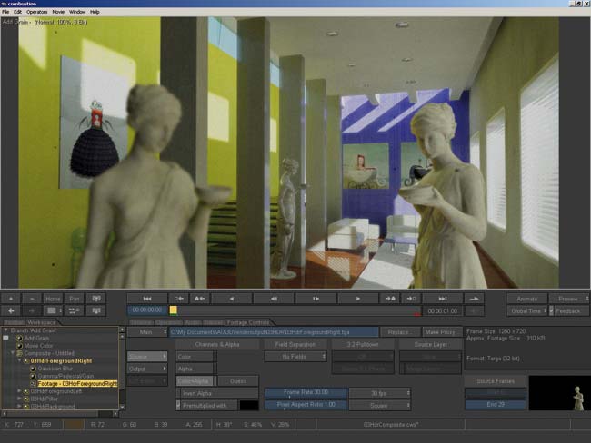
This would be incredibly useful if you had two characters in the foreground, animated over a static background. If you rendered this out in one hit, the moving characters would mean that youÝd have to recalculate the Final Gather settings at each frame, as the solution would change at each frame. Indeed, youÝd have to render the background elements out for each frame. However, with just one single frame of background rendered out, you could now quickly render your foreground character sequence out separately and composite these two together in combustion, as shown in Figure 4. Planning a compositing solution into your workflow in this way can save you time and offer huge amounts of flexibility to your final outputÍbut thatÝs a whole other subject!
Darren Brooker is a BAFTA award-winning lighting artist who has worked at many top UK studios. He works for Autodesk as a product specialist. His book, Essential CG Lighting Techniques with 3ds max, is published by Focal Press
Click here for Part l , Part ll andPart lll of this tutorial