When CAD replaced the drawing board it replicated a manual process. BIM is all about information capture and when an object changes, so does all the associated the data. Never again do you need to type the same note twice says Paul Woddy of CADline.
We all ± at least those of us over thirty ± remember the onset of the demise of the drawing board era, with die-hard supporters proclaiming that this CAD thing wonÝt take off. My colleagues and I play an amusing game at industry conferences and seminars; we count up the number of times we can overhear a conversation between two men (not a sexist oversight) debating who started on the earliest version of AutoCAD and what composition of screen / tablet / pen-plotter they first used, almost like an overgrown edition of Top Trumps. Well it amuses us anyway, mainly because we have all done it too! I suspect that many of the unwitting participants of our game are the same people that gave all the reasons why the pen was mightier than the cursor.
So why did CAD overpower parchment? Well, the main reason was to cut down on repetition. The idea of a whole troop of tracers meticulously copying a designerÝs work seems bizarre now, but I still have a dent in my finger to remind me of an apprenticeship spent amongst this now-extinct breed. The arrival of CAD was seen as a monumental change to the construction industry and businesses either changed to adapt to the new technology or faded away.
What CAD did, was to replicate and replace a manual process; that of producing drawings. We built up vast libraries of components and details so that we only had to draw something once and could forever more use the same detail or modify it quickly for a bespoke purpose. The pencil could never compete.
But is it enough to speed up the process of drawing lines? Well, no and we are all aware of the new breed of BIM packages such as Revit, that utilise 3D modelling to improve coordination, rather than just to show some fancy graphics. The fact that we change something in plan and it changes in section and elevation simultaneously, is something the industry is getting used to and the idea of a fully coordinated set of schedules is sinking in.
Again I ask, is this enough? A large part of my job is to look at emerging technologies in diverse industries and to anticipate how they might have an impact on the construction market. Already, lines start to blur between industries as diverse as electronics, satellite tracking, power generation, water usage, farming and building production and use. As they do so, information flow between interested parties will have to improve and no more so than in the convergence of our closest family; Design, Manufacture, Fabrication, Construction and Facility Management is the first phase in interoperability. The manual process of data entry needs to undergo the same revolution as the drawn line in removing repetition from the building lifecycle.
BIM is all about information capture and possibly the inclusion of the word modelling leads people to think purely in terms of the graphics with the added bonus of an automated schedule or two. Identity data can be associated with a symbol as easily as it is associated with a fully modelled 3D representation and can hence be recalled where necessary throughout the process. This data is steadfastly linked to the object and where the object changes, so does the data. Never again need you type the same note twice.
Even amongst hardened BIM practitioners, some simple techniques are being overlooked that are a major step in the right direction.
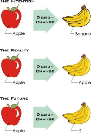
You may think at first that the graphic in Figure 1 is a rather patronising way of showing a principle, and you would be right!
What CAD has largely delivered is a simple way of swapping an apple for a banana, whether in simple 2D or parametric 3D, but what still undermines most practices is that the labelling of the fruit is a manual process and relies upon careful checking to ensure that the note reflects the diagram.
{mospagebreak}
What if the object was self-annotating however, and the note was simply a generic label and the information displayed in the note was attached to the object itself?
The last part of this graphic may bemuse, but in the self-annotating world described here, the worst case scenario is that an object does not have the relevant data entered, in which case someone must add the data.
The subtle difference here is that this need only be done once and henceforth the object will be self-aware. I am confident that you will agree with my opinion that a question mark showing missing data is better than a note showing incorrect data. When providing advice to clients I insist that the text tool be the absolute last resort when noting-up a drawing.
In the near future, manufacturer-specific objects will emerge that contain not only relevant notational data but enough codes and information that they will be able to manufacture and deliver based purely on the model content. Uniquely identified objects will then relate to external databases showing maintenance requirements for a spatially aware building lifecycle management. Components arriving on-site can be zapped to identify where in the building they fit.
It is nonsense to suggest with todayÝs hardware, the practical production of a 3D building model down to the detail of bricks and mortar, but a simplified object can still contain everything needed to communicate design intent throughout the design and supply chain. Keep the library components graphically simple but data-rich.
The proofÍ For those of you using Revit, there are many ways of achieving this but as a simple proof of concept try creating a multi-category tag with a label that points toward the Type Comments. This is one of few parameters that exist in all components. Then, within a project, add a relevant note to a wall style or even a detail component. From the draughting menu, the Tag > Multi-category tool will allow you to hover over the components and the note will appear like magic.
On a final note, I started using AutoCAD at release 2.6 and Revit at release 2.1 ± thankfully it has come a long way!