With its object-based design approach, changes made in Civil 3D automatically filter down through the design and documentation. The result is a powerful tool which shows huge potential for civil engineering projects, but lacks the maturity of a dedicated highway design package.
Last year Autodesk introduced Civil 3D, a brand new AutoCAD-based tool designed for use on a range of civil engineering projects including road design, site layout, and pipeline routing – in fact any project that requires the earth to be moved in large quantities. Civil 3D, now in its second (2006) release, is an object-based system that maintains relationships between all of its design entities, so objects such as road alignments, surface models, and building pads have built-in intelligence so they know how to interact with each other.
The result is a dynamic design environment, meaning that any changes made to one part of the design will be automatically propagated throughout the entire project. Move a road alignment, for example, and any related elements such as profiles, cross sections, and volumes are updated automatically on the fly. This not only enables engineers to make design changes efficiently (without having to rework individual lines, circles, and arcs) but helps ensure the overall accuracy of the model and all of its project data.
Working with objects
Civil 3D features a range of design and analysis objects inside its dynamic engineering model, including points, surfaces, plots, alignments, and grading. Each of these objects has a hierarchical interaction mechanism with other objects to ensure that revisions are transferred correctly between them.
Tables, object labels, and various analysis displays are also derived from the model, so if any part of the model changes, all associated parts are instantly and dynamically updated.
For example, you could move a road alignment using its grip edits and Civil 3D will automatically update proposed contours, section plots, profile labels and cut and fill volumes.
In a move designed to save yet more time, a new feature for 2006 enables multiple user access for Civil 3D objects. Users can create data shortcuts to surfaces, alignments, and profiles so that the objects can be used by multiple people across multiple drawings.
Points: Points are basic building blocks in Autodesk Civil 3D. You can use points in civil engineering projects to identify existing ground locations and design elements. Points are numbered uniquely. Each numbered point has properties that can include such information as northing, easting, level, and a description. A point displaying in a drawing can have additional properties that control its appearance, such as a point style, a point label style, and a layer. A point can be included in an Autodesk Civil 3D project so that it can be accessed by multiple users, or it can exist outside a project in a single drawing.
However, as Civil 3D is only on its second release it is still a relatively new product and lacks certain capabilities, such as being able to work directly with survey data or to carry out hydraulic analysis. Bread and butter 2D design, for which Land Desktop is better suited, will also continue to play an important role in civil engineering projects. As a result, it’s likely that Civil 3D will co-exist with Land Desktop, Civil Design and Survey for some time still, just as Architectural Desktop has with Revit in Autodesk’s architectural product space.
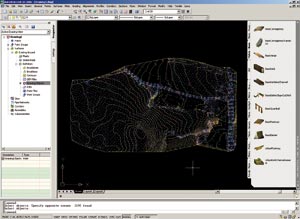
Surfaces: Surfaces are key objects in Autodesk Civil 3D. You can import surface information from LandXML, TIN (Triangulated Irregular Network), and DEM (Digital Elevation Model) files, and use points, point files, DEM data, existing AutoCAD objects, contours, breaklines, and boundaries to create new surfaces. A surface is a three-dimensional geometric representation of the surface of an area of land, or, in the case of volume surfaces, is a difference or composite between two surface areas. Surfaces can be graphically analysed to show different height ranges, slopes and watershed areas, and height ranges can be applied to ensure that spurious points do not creep into the design.
Grading: The grading tools and commands in Autodesk Civil 3D enable engineers to grade surfaces by applying criteria, such as slope to a surface or grade to a distance, to feature lines or plot lines. Grading can be analysed and balanced automatically for cut and fill and volumes or raised or lowered to achieve a particular net volume on site.
Plots: Plot objects in Autodesk Civil 3D are typically used to represent real estate plots, such as plots in a subdivision. Plot objects can also represent other features with closed boundaries, such as bodies of water and soil regions. Associated with every site is a site plot. The site plot boundary is the outermost extent of a site, containing all alignments, gradings, and plots.
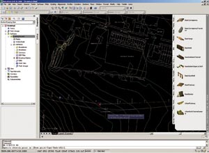
Alignments: Alignment objects can represent centrelines, carriageways, verges, highway boundaries, or construction baselines. Creating and defining the horizontal alignment is one of the first steps in highway, railway, or site design. You can draw the alignment geometry as a polyline and create the named alignment from that geometry, or create an alignment object using the Alignment Layout Tools. You can also make edits to alignments using grips, or the commands on the Alignment Layout Tools toolbar, while automatically maintaining tangency between the alignment components. For superelevation design, rules can be linked to a design standards file, such as TD9, where curves can be defined according to standard design speeds.


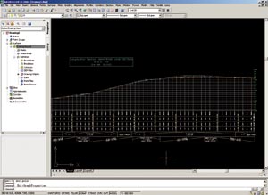
Profiles: You can use a profile (or long section) to show surface levels along a horizontal alignment and selected surfaces. You can then design the vertical alignments directly on the profile and edit via the standard alignment tools, grips, or the tabular editor.
Sections: You can use sections, or cross sections, to provide a view of the terrain cut at an angle across a linear feature, such as a proposed road. Typically, sections are cut across horizontal (plan) alignments at a specified chainage interval. These sections are then plotted, individually for a chainage, or as a group for a range of chainages, depending on the purpose of such plots. The Quantity Take Off tools can also be used to generate section volumes from the design, for both earthworks and materials.
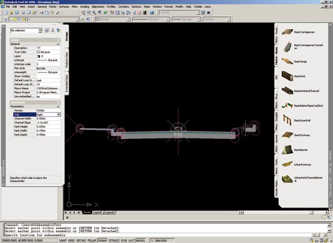
Assemblies and Subassemblies: Assembly and subassembly objects enable you to create the primary structure of an Autodesk Civil 3D corridor model. Assembly objects contain and manage a collection of subassemblies that are used to form the basic structure of a 3D corridor model. Adding one or more subassembly objects, such as carriageways, kerbs, and slopes, to an assembly baseline creates an assembly object. This forms the design for a corridor section.
Corridors: A corridor model brings together various Autodesk Civil 3D objects and data, including subassemblies, assemblies, alignments, surfaces, and profiles, and is applicable to any linear ground-based feature. Corridor objects are created along one or more baselines (alignments) by placing a 2D section (assembly) at incremental locations and by creating matching slopes that reach a surface model at each incremental location. Edits can be made on a section by section basis to fine tune the design.
Pipe networks: New for 2006, you can use Autodesk Civil 3D pipe network features to draw 2D and 3D models of utility systems, such as storm sewers, wastewater sewers, and more. You can create pipe networks from design catalogues, edit, and delete them in plan view and use profiles and section views to display pipe network parts in profiles and section views. Changes made to pipe networks in plan view are dynamically updated in the profile and section views.
You can import or export pipe network data using Autodesk LandXML format, or analyse pipe network data through an API interface or with support from external, third-party analysis programs.
Drawing standards
Each object type includes user-defined settings that control layer, colour, font, label content etc, and styles can be used to efficiently manage object appearance. When you create a new object, you can apply a predefined style for its display. Later, you can apply a different style to suit the needs of different users or different project stages. For example, you can have different styles for existing ground and finished grade surfaces, or different styles for the initial drawing/laying out of parcels and the presentation/plotting of parcels.
Styles can also be used establish standards throughout the engineering workflow, ensuring consistency in drawing creation and presentation.
Conclusion
Just as Autodesk did with its architectural software products (Architectural Desktop + Revit) a few years back, the company has introduced Civil 3D to run alongside its previous generation product, Land Desktop. While Land Desktop still excels in certain areas, Civil 3D is the future of Autodesk’s ‘Infrastructure’ software division, and the result is a powerful system that gives engineers the flexibility to try out different design concepts and fine tune projects without having to do major amounts of rework. So what’s the catch?
While Civil 3D excels in key areas of civil engineering such as site layout, it doesn’t yet offer the same depth of highway design functionality you’d expect to find in more mature products such as Bentley’s MX Road. For example, there are no dedicated tools for creating roundabouts or junctions. In addition Civil 3D currently lacks the ability to work directly with survey data, and areas such as street furniture or hydraulic analysis have yet to be catered for directly.
As with all new technologies, Civil 3D will require many civil engineers used to more traditional CAD tools to make a substantial leap into the world of model-based design. It’s an entirely different way of working with a different workflow, techniques, and indeed the requirement of a different mindset. But with sufficient investment in training and development, it has the potential to transform the way civil engineers work where the intelligent relationships between objects not only help improve project data accuracy, but also efficiency in the design process.


