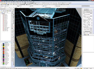
MicroGDS is one of the AEC industry’s long-standing CAD systems, and has a loyal customer base that benefits from its multi-user capabilities. Recently under new ownership, the developers are now looking to push the product forward into new areas, writes Greg Corke
MicroGDS’ roots stem back to the 1980s and over the years the CAD package has built a reputation for drafting efficiency, team collaboration and presentation graphics. Its user base comprises architects and multi disciplinary engineering firms and often-quoted customers include HLM, The Hillier Group and Scott Brownrigg.
While MicroGDS has both 2D and 3D capabilities, it is predominantly a 2D product and its approach to collaboration is simple, yet effective. It enables architects, electrical engineers, structural engineers and building services engineers to all work together on a project concurrently and it does this by splitting each MicroGDS project into many layers that are stored in a central project database.
While layers can be broken down by discipline, they can also be defined by other aspects of the design, such as a floor level, a specific part of a building, or even a single electrical circuit. At any one time, only one user is given ‘write’ access to an individual layer, but the others can still reference this layer and use it as the backdrop to their work. Any changes made to a layer will be automatically updated on other users’ screens once the layer is refreshed.
Working in this way, often with geographically dispersed design teams, communication is key. Here MicroGDS provides built-in ‘chat’ functionality so team members can keep up to date with who is working on what, and where they are in the process.
The new release
Version 10 of MicroGDS was released over two years ago and the 2010 release is currently in the final stages of development, due to be released early 2010. As a result, it is important to note that this review is based on beta code, but Informatix expects that all of the functionality covered will be included in the final shipping version.
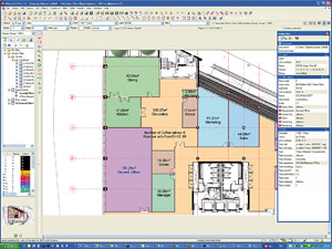
While Informatix encourages third-party developers to use MicroGDS as a platform for their own CAD-derivative applications, the company has also developed its own vertical application. Informatix Facilities Management (FM) provides a broad FM technology to cover anything from simple maintenance scheduling to enterprise-level asset management.
The software is an extension of MicroGDS Plus and stores graphics and numerical data in a central SQL database. It features asset management tools, scenario analysis, cost automation, asset capture through bar code technology and a wide range of reporting tools. It also includes the ability to view assets graphically and can integrate with a wide range of third party applications including other CAD programs, asset registry and enterprise software such as SAP and Oracle. Users will also be able to add functionality to the FM solution through the Application Development Kit (ADK) in MicroGDS 2010.
The major concentration for the new release is on providing productivity updates across the board, but the development team has also been looking to introduce a number of new technologies. This includes the ability to create intelligent parametric objects, and Informatix sees this as a first step to offering so-called Building Information Modelling (BIM) functionality inside the software.
However, the company has also introduced a new ADK (Application Development Kit) so MicroGDS can be exploited by third-party developers and used to build new CAD-focussed applications.
Productivity enhancements
A lot of the enhancements in this release are about increasing speed and efficiency in everyday tasks and we will deal with each of these in turn.
64-bit computing: MicroGDS has always had a relatively small footprint, particularly as users only load in the layers that they need to work with, as opposed to the whole project. However, with Version 10 some users that work with extremely large 3D models were running into memory limits, particularly when rendering. Now with 64-bit support, memory limits have been removed and MicroGDS 2010 can address more than 4GB of memory, providing your workstation is fully equipped and running a 64-bit Operating System.
Customising the interface: MicroGDS preferences used to be stored in the registry, but this often caused headaches when deploying company or project standards, as everything had to be customised from scratch. Preferences are now stored in a hierarchy of XML files, which can be plugged into the system as and when required.
At the ground level, personal settings enable users to customise the user interface. These can be accessed from anywhere on a network so users can hot desk and are still be able to access their familiar working environment.
Moving up, preferences can also be controlled at a project level or domain level. Here the CAD manager can enforce drafting, naming or layer conventions and certain commands can be switched off and preferences locked down.
This ability to control standards and deploy them with ease will be of particular interest to those working on multi-site, multi-discipline projects.
Link resolution: MicroGDS can reference all manner of files inside each drawing, including line types, fonts, raster images, and instance files (similar to AutoCAD XREFs). Often, if drawing files are moved or if a server is not available, these links get broken and the user is warned of this when opening a drawing. In Version 10 the user would either have to fix any broken links there and then or cancel all the broken links and remember what was missing and fix them later. However, this would also involve going back into each individual command making the process inefficient.
In the 2010 release, missing links are gathered together and stored in a single dialog box. This can be accessed at any time by double clicking a little yellow triangle that resides at the bottom right corner of the screen with each missing link able to be fixed direct from the list. Working in this way, problems can be fixed at the pace of the user. It is a small enhancement, but one that will allow users to get on with the job at hand without getting bogged down in administration.
Axis control: Previously, MicroGDS had a single global axis system, but this made it difficult if users were flipping between views — interiors and site plans, for example — as the scale and axis origin had to be changed. In the 2010 release every window, or every view of data, has its own axis system, which reduces the possibility of errors creeping in by accidentally drawing at the wrong scale, or from the wrong origin or orientation.
Printing and export: MicroGDS layers are typically combined together to form a window definition — or a view of a drawing. Each layer can appear multiple times in a window and specific attributes or object names can be filtered out of each. This means window definitions can get quite complicated, especially if you have a large number of layers and want to combine them in different ways. Previously, when it got to the production drawings stage, in order to define plot styles, the actual window definition had to be changed or a new one created. Now the final output can be tweaked specifically for plotting purposes and the working window used for draughting can remain untouched.
Once the final production drawings have been created, the next stage is to print them out. Frequently, sets of drawings need to be produced and to deal with these more efficiently Informatix has introduced a series of batch commands. ‘Batch Publish’ takes what you see on screen and renders it to a file, while ‘Batch Export’ takes the underlying model and a window definition and puts that in another file. Output formats include a choice of PDF, DWG, DXF, DWF, 3DS, SVG and all the common raster formats.
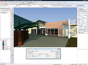
Individual export settings can also be saved in an XML file. For example, if a DWG file is being exported for a customer, users do not need to remember whether or not to explode XREFs or include linestyles; but simply recall the XML file.
Rendering: The rendering engine inside MicroGDS 2010 has been updated to LightWorks 8.1, a ray trace and radiosity renderer from LightWork Design. The two main additions are progressive rendering and ambient occlusion.
Progressive rendering starts off with a rough pass and refines the render over time. This enables users to get a good idea of how the final render will turn out without having to wait for it to be completed. Ambient occlusion is designed to better simulate the way light radiates in real life, especially off non-reflective surfaces.
When implementing LightWorks 8.1, Informatix also looked at making rendering more accessible to non-expert users. This was done by finding a balance between the level of control and the achievable quality of the final render. To do this, certain commands have been hidden or grouped into a single command, rather than giving users control over every single variable.
ADK — Application Development Kit: The ADK is a .NET library of functions that allow users to deal with MicroGDS data in different ways. The integrated ADK allows users to develop functions that sit within MicroGDS, while the standalone ADK, which is a brand new addition for the 2010 release, enables customers to build an application that does not need MicroGDS, but can utilise its data.
This means bespoke applications can be created with their own front end, for example, for building services, facilities management or more niche applications, such as redlining or surveying. In these instances, applications can also be designed specifically to run on low powered laptops as many of the more heavyweight functions such as 3D or rendering are not required. The integrated ADK development tool ships free with all versions of MicroGDS 2010.
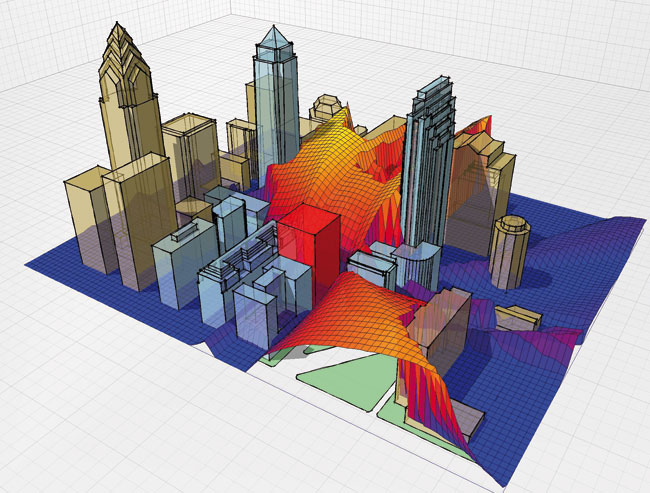
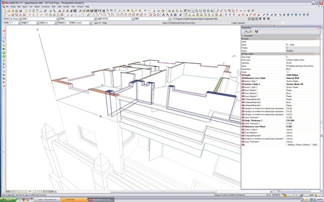
Intelligent objects: New for the 2010 release is the ability to generate intelligent parametric objects that can automatically adapt to their environment. This forms the basis of a new collection of so-called BIM functionality inside MicroGDS 2010 and is enabled by technology from the new integrated ADK.
Informatix is building up a library of IFC (Industry Foundation Class) compliant objects. Each object is an independent ADK function and contains a number of attributes, some of which can be linked to each other parametrically. Each object also possesses a ‘behaviour’, so doors, for example, will automatically insert into walls and create openings. Then if the door is deleted or moved, the wall will automatically heal.
Each object features different representational graphics for each view, such as individual views for general arrangement, 3D, elevations, and sections. The representational graphics of objects can also be set to change according to scale.
The number of objects supported in MicroGDS is still relatively small and currently only includes walls, doors, windows, slabs and staircases. In addition, this content is not yet linked to specific manufacturers’ products.
However, the generation of other objects, including curtain walls and roofs, are already underway and these will be rolled out in 2010. Informatix is also looking at ways to extract standard Revit objects using IFCs.
As each object is an independent ADK function, the user can simply plug them into MicroGDS as soon as they become available on the MicroGDS website. With the ADK it is also possible for users to create their own custom objects.
Conclusion
With new owners looking to push the product forward, MicroGDS is in a state of transition and there are three driving forces behind its development.
First, for existing users, there is a focus on making the system more efficient and its users more productive. This is being delivered through commands such as batch processing, axis control and preference management and while these are not headline grabbing enhancements they are sure to be embraced by the current user base.
Second, while the introduction of intelligent parametric objects will give Informatix the right to market MicroGDS as a so-called BIM solution, albeit one in its embryonic stages, the technology stripped back to basics is of more importance. For those that use MicroGDS as a production draughting system, the ability to model intelligent walls, doors, and windows will almost certainly increase draughting efficiency, and despite ticking all the right BIM marketing boxes, it should not cloud the true benefits of such a technology.
Third, the introduction of a standalone ADK means that third-party software developers can more easily develop their applications on top of MicroGDS or as a standalone application. From surveying and building services to structural engineering and FM, the scope is wide. With the new owners of Informatix open to negotiation on licensing costs, developers that may have been marginalised by Autodesk and Bentley in recent years, may now see MicroGDS as an attractive platform on which to develop more cost effective CAD-based solutions, either with standalone or multi-user capabilities.

