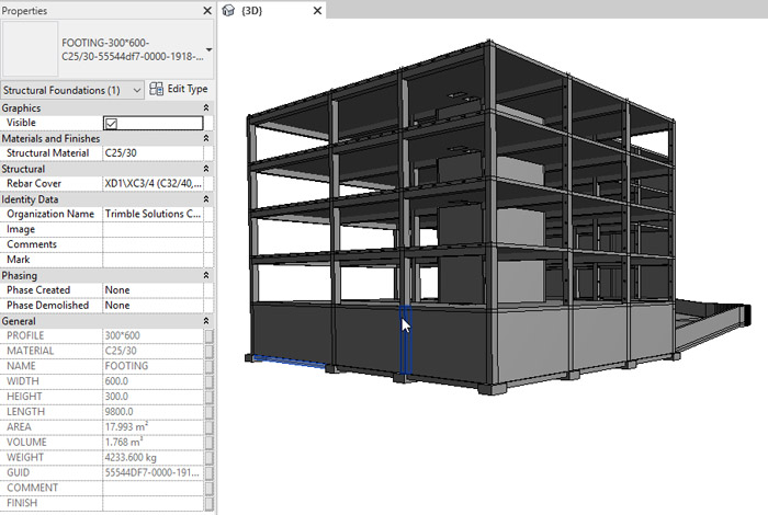
With its latest Tekla promises to make engineers more productive. Accelerated production of GAs is the most obvious benefit but the end goal is to build confidence in the 3D model, so data can flow freely from design office to site
With Tekla Structures being one of the most mature structural BIM tools on the market, by now one would think it would have 2D drawing production nailed completely. But the latest 2019 release shows there is still room for innovation. It also demonstrates how important the humble 2D drawing continues to be. Tekla Structures might excel at delivering construction ready 3D models, complete with every nut, bolt and weld, but the 2D drawing is still considered to be the bread and butter deliverable for the AEC industry.
For some time now, Tekla Structures has offered optimised drawing production for fabrication drawings, including pre-cast, cast in situ and steel. Simply create a model, hit a button and the software automatically runs off all the drawings. All the user needs to do is a little bit of tidying up and sometimes none at all. This level of automation is hardly surprising, as much of the work done by fabricators or contractors is based on project-specific templates and is highly repetitive.
For engineers, things are a bit different, as they spend a lot of time producing GAs, and as each project varies, often working with different architects, it’s hard to build true automation into the process.
What Tekla has done for this new release is add tools to help reduce the amount of manual clean up needed on GA drawings. Users can now clone annotations, such as dimensions and marks, as well as linework and hatching styles. So, once things have been laid out correctly on one part of the drawing, they can then be applied to other similar areas – bit by bit or all in one go.
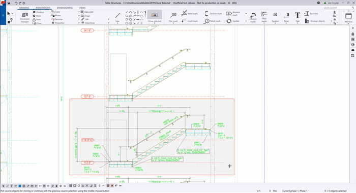
With a staircase, for example, simply annotate on one floor, adding info for risers, angle, tread, stringer, fixings etc., then clone those annotations to the second, third or fourth floor. Previously each floor had to be done manually, which was very time consuming (and monotonous). It’s important to note that this isn’t just copying and pasting dumb geometry. All cloned annotations are made fully associative to the model objects in the new location. For example, part marks and information about levels and heights will be automatically updated. Then, if any changes are made to the model, the annotations will update accordingly.
As one can imagine, this works best with repetitive structures, such as foundation plans, anchor plans, rebar placement drawings or elevation drawings. But the geometry doesn’t have to be identical, only similar. The software is smart enough to handle variations. Of course, for this feature to work reliably, annotations do need to be associated with the correct objects. For example, a single point on a 2D drawing could relate to many things – a plate, a beam corner point, or even a grid. Now with the new version, users can specify exactly which objects dimension points should follow.
The drawing environment also gets the kind of search and edit capabilities you’d typically find in the modelling environment, with an enhanced version of the Drawing Content Manager. When first introduced in 2018, it allowed you to check and edit objects and drawing content in the current drawing.
For example, you could easily check which objects were missing marks, quickly highlight objects of a certain type, or globally change the way they were displayed. This was limited to a default set of properties but now you can add any property that exists within Tekla Structures, even custom properties. For example, you can now quickly identify items that need special notes, in order to draw attention to them – beams over a certain length, for example, or rebar over a certain weight that will require special lifting on site. You can also use it to quickly add notes to custom objects like lock nuts or objects with special paint finishes.
There are a few other drawing related updates. GAs can now be rolled back in time, so if someone has made an error when editing a drawing, you can revert to any number of previous versions. You can also compare versions by overlaying one over the other.
Third-party data
According to Tekla, its users are increasingly working with third party data, including BIM objects and those exported from mechanical CAD systems in formats like IGES and STEP. However, the quality of these objects can vary. Some can have faces missing, which means they are not solid. Previously, these may have looked OK in certain views, but in other views, including details and section, the objects may have completely disappeared. Now, the software ensures that these objects are displayed in all views regardless. Tekla says this tool will prove particularly useful when importing complex formwork models for cast-in-place concrete construction.
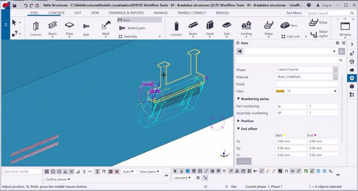
The way third-party objects can be positioned within the software has also been improved, using direct manipulation handles and interactive preview. In the past this type of control was only possible for native Tekla custom components, so users first had to convert the third-party object and add it to the custom component library, which took time. Again, this is especially useful when working with cast-in-place concrete structures, says Tekla.
The way Tekla Structures manages IFC files has also been enhanced. When importing a revised IFC file, you’ve always been able to compare old and new to see what’s changed. Now, rather than having to go through every change, you can tell the system to look out for specific things like changes in length or area. You can also set tolerances, so it doesn’t pick up those which, in the grand scheme of things, are insignificant.
Improvements have not only been made to data import, but export as well. While Tekla is very much committed to IFC for sharing data, some clients specify RVT files as the project deliverable, so the new Revit Geometry Export tool allows firms to comply without having to invest in a license of Revit Structures. The extension, which is powered by technology from the Open Design Alliance, is available through the Tekla Warehouse.
Trimble Connect enhancements
Trimble’s collaboration platform, Trimble Connect, has also seen some significant enhancements. First, it is now much better at viewing colossal IFC files, which can be hundreds if not thousands of megabytes. Rather than trying to open a heavy IFC file directly which could take minutes, or might not work at all, a new viewing technology converts the data into a much lighter format without losing fidelity. This feature, currently in beta, should be particularly beneficial when taking data on site on mobile devices.
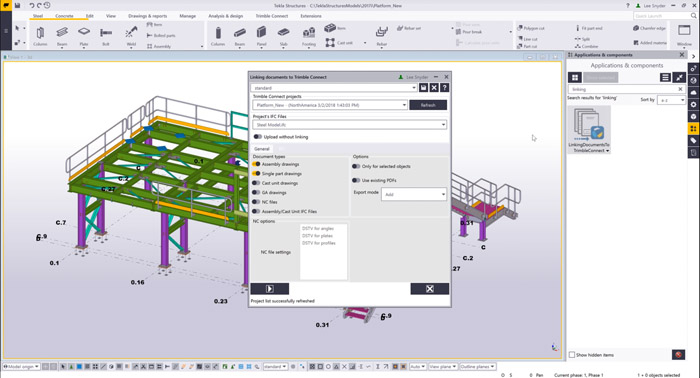
The workflow between Tekla Structures and Trimble Connect has also been enhanced. It’s now possible to upload NC files and drawings (assembly, part or GA) to Trimble Connect and link them to the respective objects within the model, all in one go. This is a neat feature for collaboration as it gives the whole project team easy access to in-context documentation. In short, the 3D model becomes the index for project deliverables. Simply click on a beam, for example, and you can instantly view the associated data.
The new release also allows you to overlay 2D information on the 3D model, which can further aid checking, validation, and communication.
Taking data on site
Once data is inside Trimble Connect it can be pushed out to many different devices for use on site. This could be a standard tablet for viewing 3D models and drawings or an Augmented / Mixed Reality device to see construction ready models in the context of where they will be built.
Trimble is investing heavily in augmented / mixed reality and has developed two hardware devices. The first is Trimble SiteVision, a handheld system that combines a 2D display with Trimble’s centimetre- precision Catalyst GPS. The second is the Trimble XR10, a wearable mixed reality hard hat built around Microsoft’s HoloLens 2. Both are in early development.
Visual enhancements
For the new release, Tekla has turned to game engine visualisation and made two new visualisation extensions available through the Tekla Warehouse. The Tekla Structure Visualizer and Trimble Connect Visualizer are both based on Unity and allow users to visualise large structural models much more realistically than can be done in the viewport and also create stills and animations for project presentations and marketing.
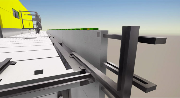
The push button workflow for Tekla Structures Visualizer is very simple. A base set of materials – steel, concrete, grass, timber, etc. – are automatically mapped. Users can create animations simply by placing the model in key positions and the system then smoothly transitions between them. The animation can be played in the software or, if a video file is required, captured using third-party software, such as the Xbox technology built into Windows 10.
The Trimble Connect Visualizer is similar but opens up the model for sharing and also works with referenced models, such as IFC or RVT.
Bridge Creator
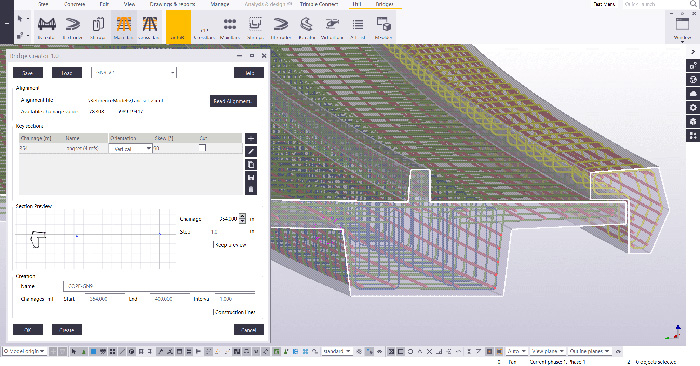
The Grasshopper-Tekla live link, introduced in 2018, gave engineers access to powerful algorithmic modelling tools, which could be used to good effect for bridge design. Now Tekla has given bridge designers their own ‘Bridge Creator’ tool that is designed to make early phase design faster and easier.
In essence, users can take a road/rail alignment from a civils design tool in LandXML format, then automatically apply key sections along that alignment to define the bridge deck.
Steel modelling enhancements
Tekla Structures now has enhanced modelling tools so it can better handle bespoke steel work such as bent plates or conical plates. This could be useful for highly architectural staircases, for example, or ductwork corners and flues.
It’s also now possible to add self-tapping screws and nails to the model without creating a hole. Previously, this was done automatically, regardless of the type of fastener. Now you can ensure that the model is completely accurate, which is particularly important when generating Bills of Materials or NC files.
Welds have also been enhanced to allow users to more accurately define them within the model. Previously, fabricators would often define welds simply by adding manual marks to drawings. Now, there’s a growing demand to share more accurate models, improve traceability and use robots, which rely on precise information.
Pre-cast concrete
Version 2019 introduces a new design-to-cost tool for the pre-cast industry that allows engineers to compare different alternative designs and find the most cost-effective solution. Users define the unit costs for different element types in the model and the system then costs up the whole model or selected parts. Tekla says that because you can immediately see the cost impact of the changes in the model, you can more easily find the most economical precast solution for your projects.
There are also enhancements to the tools that automate modelling and detailing for double wall structures. New Half Slab Reinforcement tools let you automatically add optimised, detailed reinforcing and braced girders to half slab floors.
Conclusion
Structural engineering continues to be heavily reliant on 2D drawings. Even if an engineering model is available, most contractors or fabricators still prefer to build their own from scratch.
It’s easy to extol the virtues of model-based deliverables where data flows seamlessly from design office to contractor/ fabricator, but for this process to be fully embraced, everyone needs to have confidence in the accuracy of the data. But why should they, when far too often the 3D engineering model is just a starting point and 2D drawings become disconnected when polished in a 2D CAD tool like AutoCAD?
Tekla Structures is renowned for its ability to generate detailed fabrication drawings quickly. Now, by delivering new tools that can dramatically accelerate the production of GAs, it is looking to build a stronger presence in the engineering sector. The big challenge will be getting engineers into the mindset that because the model and the drawings are inextricably linked, both assets can be shared. Then, as a next step, if you remove the drawings altogether, you remove the traditional time-consuming approval process.
Of course, for some firms this is already becoming a reality. There are engineering consultancies and fabricators effectively working on the same Tekla Structures model via Tekla Structures Model Sharing and Trimble Connect. So, everything just goes straight through and design changes are also dealt with much quicker.
The next step is to take those models on site with data flowing seamlessly, so what you model in Tekla Structures is exactly what is built. Trimble is putting things in place for what it calls the Constructible Process. And then, of course, the industry needs to join the dots.
If you enjoyed this article, subscribe to our email newsletter or print / PDF magazine for FREE

