Tekla Structures is an end-to-end structural BIM solution providing a dedicated 3D modelling environment for conceptual design, engineering, round trip analysis, detailing and beyond. Greg Corke takes a closer look at the latest release, version 14.
BIM (Building Information Modelling) is at a tipping point in the architectural sector with increased adoption of products like Revit, Bentley Architecture, and ArchiCAD. But while architects are only starting to realise the benefits of intelligent object-based design, their colleagues in the structural sector have been reaping the rewards for much longer.
Virtually all steel fabricators rely on intelligent 3D models to produce accurate Bills of Materials (BOMs) and cutting lists / NC code, while consultant engineers exploit 3D to design and analyse increasingly complex structures. But getting the two disciplines to work together with the same 3D data is another matter entirely and one of the underlying ambitions for structural software developer, Tekla through its Tekla Structures product.
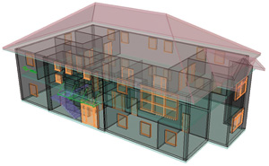
Structural BIM, as Tekla defines it, covers the entire structural design process from conceptual design to detailing, fabrication and erection of all multi material elements. However, itÝs not just about the structural engineer passing on a model to the steel fabricator, but providing a single design environment in which concrete, steel and even timber can happily co-exist.
Tekla is a Finnish company by descent and its background lies in structural steel detailing through a product called XSteel, one of the first commercially successful 3D detailing applications on the market. In 2004 the company combined XSteel with its Xengineer product, a parametric 3D modelling package for engineers, and Tekla Structures was born.
Like Revit Structure from Autodesk, Tekla Structures is a structural BIM application, which enables engineers to create intelligent physical and analytical structural models for design. However, it also offers a highly capable steel detailing element, combined with precast concrete detailing, reinforced concrete detailing, and into the realms of project management.
Tekla Structures is used in over 80 countries worldwide on a huge range of projects ranging from Wembley Stadium and the Beijing Olympic Stadium to New YorkÝs Freedom Tower and Leadenhall in the City of London. Its ability to model complex structures whilst keeping the file size small is a particular draw for the product. For example, the model for Wembley Stadium was only 70MB in size.
The system is modular and the number of options available is a little overwhelming, but this means users can tailor the application for many specific roles without shelling out for the entire software package if they are only interested in certain elements. There are seven configurations in total: Full Detailing, Steel Detailing, Precast Concrete Detailing, Reinforced Concrete Detailing, Standard Design (will be called Engineering in 14.1), Project Manager, and Viewer.
Design and modelling
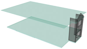
ÙStandard designÝ is the module of choice for consulting engineers and the starting point for any structural design project in Tekla Structures. It provides all the tools required to build up a structural BIM model and offers Ùround tripÝ analysis links to many of the leading structural analysis applications. Tekla Structures models can be built from scratch or based on referenced architectural or other 2D drawings or 3D models (DWG, DGN, IFC, etc). These 3D models can be made transparent to improve clarity, clip planes can also be used to expose elements through sections and clash detection carried out between models. As architectural models are continually changing there is a neat utility that enables users to compare two referenced 3D models and show only the changed objects.
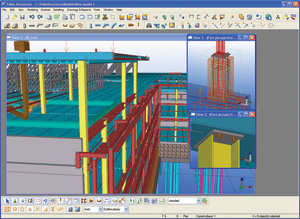
Grids are essential, regardless of whether referenced data is being used or not. These are even more important in Tekla Structures than in other structural applications as they not only provide reference points for structural components, but can be used to generate different named views for each of its viewports. For example, named views can be created for specific sections through a structure and it can also be used to define plan views at specific elevations or floor heights. This is likely to take a little getting used to but itÝs an extremely powerful capability.
Pretty much anything can be modelled in Tekla Structures: beams, columns, slabs, walls. These can be chosen from an extensive library of industry standard components and include standard UK & European sections, cold rolled, and precast concrete, but custom profiles and freeform components can also be modelled. This makes Tekla Structures particularly attractive for use on complex projects.
In a typical workflow components are laid down onto the grid, offset, or snapped to construction lines or reference elements. Users can work in 2D or 3D at the same time and even start in one view and finish in another ± it is that flexible.
Component properties, such as size, length, and material, can be defined prior to modelling or edited at a later date. Group edits are easy and users can choose which attributes to change. For example, it is possible to change the length of a group of beams without changing their individual shape or sizes. All the usual copy, move, and array commands are available to help users quickly build up the structure. There are very few limits.
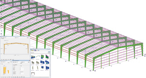
Components do not have the same level of intelligence as they do in other BIM applications. For example, a beam does not automatically trim when it is attached to a column. However, there is a number of different ways to build in connectivity between components, so if a beam moves or changes shape the column adapts accordingly.
With more control over how components interact, Tekla Structures offers much greater modelling freedom. The downside is that users will have to invest more time to ensure that the geometry behaves how it should when edits are made.
{mospagebreak}
Tekla Structures uses a central database to store all of its data. At the conceptual stages of design, this means several engineers can work in the same environment without having to break the model down into chunks. As data is saved a prompt appears to enter an optional revision comment explaining the changes. At the same time, users are notified of changes made by other engineers. Working in this way a full audit trail is made available for the project, but care still needs to be taken to co-ordinate work. Tekla Structures does not have a dedicated mechanism to enable engineers to communicate in real time. Instead, use of applications like Instant Messenger is common.
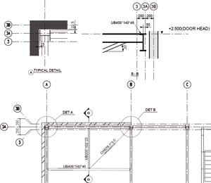
Steel detailing is a major strength of the system and it includes hundreds of different types of 3D parametric connections. These can be generated automatically through customisable rules and are based on Green Book codes. They can be adapted by the user and parametric and non-parametric connections can also be created from scratch and saved in a custom library. A number of parametric custom components, such as Curtain Walling, Staircases, Trusses, and Precast Floors, are also included.
Analysis
TeklaÝs BIM ideology of sharing structural data throughout all stages of the design process is also applied to analysis. Round trip analysis is provided for a number of leading applications, including Robot, STAAD, S-Frame, and SAP2000. Engineers can export the BIM model from Tekla Structures, analyse the structure in a dedicated analysis application, tweak the design as necessary, then bring it back into Tekla Structures and accept or reject design changes (individually or globally). For analysis applications where direct links are not available (such as RAM) Tekla Structures also supports the CIS/2 and IFC interchange standards. In this case design changes need to be manually updated in the Tekla Structures model.
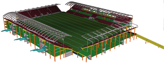
Forces and load conditions can also be assigned inside Tekla Structures and taken into the analysis package. This streamlines workflow, particularly if there are multiple design iterations. However, many engineers still prefer to manage loading, and instead load cases inside an analysis application.
Structural analyses requires a dedicated analytical model. Unlike Revit Structure, which automatically builds an analytical model in the background as the physical model is built, analytical models are created as and when required. The engineer can create multiple models for different types of analysis (steel frame, beam design, concrete slabs) and can define exactly which components are included in each. This means the best analysis application can be used for the job at hand.
Inside Tekla Structures Analytical models can be viewed alongside the physical model and the engineer is afforded much control over the positions of nodes (the top, bottom or neutral axis of a beam), the type of joint (fixed, pin) and the level of fixing. Additional nodes can be added if required and structural elements can also be combined as one affording much flexibility.
Drawing and reports
With a central database containing all the structural information, drawings are produced as ÙsnapshotsÝ of the 3D model. If the model is amended, these changes are automatically highlighted in the drawing with a revision cloud. These remain until the drawing is re-issued.
Details and sections can be created from other views and if they are placed on another drawing sheet they are automatically referenced in the original drawing.
When inside a drawing it is not possible to move beams, columns, etc so the physical model canÝt be edited in this way. However, CAD tools can be used to add lines and text to drawings.
Drawings can be based on templates with title blocks automatically populated with project information and anything in the model can be scheduled. Dimensioning is automated, as can be the creation of close-up views of details.
The engineer is afforded complete control over how each detail and component is displayed but if something has not been modelled to the required level of detail, drawings can also be augmented with ÙdumbÝ 2D details, though these are not linked to the project model.

In addition to drawings and schedules, Tekla Structures can generate a wide variety of reports in HTML, .XLS and .TXT formats, based on the model as a whole or for individual components. These can also be used to check the model for accuracy before it goes downstream. For example, an engineer could use a report to instantly see if columns are on a grid and then automatically zoom to the problem area.
CNC code and steel management
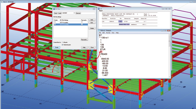
For CNC (Computer Numeric Control) code generation, which is used to drive shop machinery tools to fabricate steelwork, the system supports DSTV standards. In addition, Tekla Structures supports FICEPÝs scribing technology, which scribes directly onto steel to indicate the required layout locations and aid in construction on site. Part marking, layout lines or welding symbols can all be added.
Tekla also works closely with Vela Systems to support its RFID (Radio Frequency IDentification) technology. This enables all components to be tracked and managed from shop to site. This information can be visualised in the model environment or over the web using the free web view.
Concrete detailing
While TeklaÝs strength historically lies in steel, its Structures product also includes 3D detailing tools for reinforced and pre-cast concrete. Whereas 3D steel detailing is commonplace, RC detailing has largely remained a 2D practice so doing everything in a 3D environment is an interesting proposition. As with steel in Tekla Structures, the modelling process is flexible and the detailer simply lays down bars with the system automatically recognising shape code and positioning according to pre-defined cover thickness. Attributes such as grade, size, and number of hooks, are all controlled via dialogues.
The system also features a number of standard objects and can automatically detail pads, strip footings and beams, among others. Detailing macros are provided for wall panels, windows and other details. A drawing wizard is included for producing reinforcement drawings, formwork drawings and rebar schedules, and NC code can also be generated for bars.
Conclusion
Tekla Structures is a vast product that covers the entire structural design process in a single environment. It enables a single BIM model to be used from the conceptual stages right through to fabrication and beyond and its ability to re-use data through the design, analysis and detailing phases and model in steel, concrete and timber is somewhat unique in the industry. While other structural BIM systems offer capable modelling and round trip analysis, they do not provide such powerful tools for the detailing phase, a capability on which Tekla Structures was founded.
Tekla Structures scores highly in structural design, but it loses out when it comes to sharing data with other AEC disciplines. While it supports the capable IFC standards, there is still no substitute for sharing data with architects and building services engineers in native formats, such as Revit and MicroStation, and this will become increasingly important in the coming years as BIM grows.
In terms of modelling the product is extremely powerful and users only need to look at the range of structures that have incorporated Tekla Structures to see how adept it is with dealing with complex forms. The downside of this modelling freedom is that structural elements are not automatically constrained, so a disciplined approach to modelling is essential to ensure connectivity is maintained. Without this users are missing out on the major benefits of structural BIM, such as adaptability, accurate drawings, BOMs and cutting lists.
Delivering such a powerful system for structural design is a major achievement for Tekla. The software does an excellent job of bridging the gap between design and fabrication and through its single environment provides the perfect conduit for data to flow smoothly from engineer to detailer. Most importantly, though, it has the potential to simplify the management of an often fragmented process, leading to enhanced collaboration, better designs, reduced times, and of course lower costs.

