Group2 is using Reality Computing to bring control and efficiency to structural steel development and construction to UCAMA’s retrofit project. Sponsored content
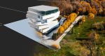
During the 19th and early 20th century, Ukrainian immigrants were one of the largest ethnic groups to settle in the Canadian prairies, and they had a significant impact on the region’s social, cultural, and economic development. In 1972, the UCAMA was created to preserve the history and culture of Ukrainian Canadians. Located in Edmonton, Alberta, UCAMA’s collection has now outgrown its original facility and the museum is renovating an historic building in a prominent downtown location to serve as its new home.
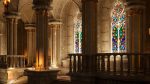
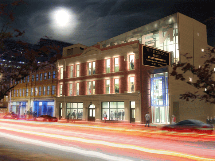
The property — a hotel built in 1911 and an important part of Edmonton’s early social and commercial life — is a three-storey brick building. UCAMA preserved the historically significant parts of the building, particularly the street-facing façade and other original brick components including much of the remaining facade and some interior walls.
The rest of the building was dismantled to accommodate a 21st century, four-storey structure and a below-ground parking garage. UCAMA’s integrated project team, including Group2 Architect Interior Design Ltd., used reality computing to capture 100-year-old as-built conditions and guide the creation of an Autodesk Revit building model for project design, documentation, and coordination.
A new beginning
The design of the new museum began in 2006, but funding issues put construction on hold. In 2012, construction of the museum began by dismantling portions of the existing building and temporarily shoring up the remaining brick walls and facades. The project team then faced a serious issue: how to document and create a digital representation of these as-built/as-found conditions for construction planning and coordination.
“Initially, we had a surveyor produce measured drawings of the building. During our design we tried to use Revit software to create a model from these drawings,” explains Allan Partridge, Group2’s executive director of integrated practice.
“But we would only take the model so far, as nothing was plumb or square in this old building.” However, the team knew that the coordination of the new structural steel within the remnants of the existing structure would be one of its biggest challenges and posed the largest risk from a scheduling point-of-view.
So the team decided to laser scan the inside faces of the remaining walls to capture extremely precise geometrical data for the surfaces where the new structural frame ties into the old brickwork. A targeted registration process was used to capture the building with 145 mm diameter spheres mounted on tripods.
Spheres were positioned on both floors at the top and bottom of stair runs and floor openings where multiple scans would be taken and then registered accurately between floor levels.
The scanning was performed by SiteBIM, a 3D laser scanning and “As Is” BIM modelling service provider. The registration software used was FARO Scene.

Structural coordination
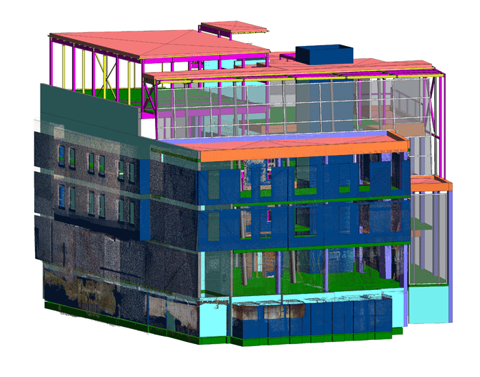
The project team used the point cloud and Revit software to model the remaining structure and create a precise as-found record of the building, giving them an exact record of what was there — complete with all the flaws and imperfections expected in a century-old brick structure.
This Revit model was the basis for Group2’s architectural design as well as ongoing project coordination and clash detection. This master model also contained major concrete structural elements.
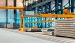
The existing brick walls are tied into concrete up to the second level, and into steel on the upper levels. The concrete work was self-performed on site, whereas the steel was fabricated offsite.
Throughout the construction, Group2 linked two other models to its master Revit model: 1) the original point cloud (saved as a separate Revit model) for visual context, and 2) the steel fabricator’s model to verify if the new structure would interfere with the existing brickwork.
The structural model was supplied to Group2 by the project’s structural supplier, Collins Industries. Collins used Tekla software and would convert that model to an IFC format, which Group2 linked to its Revit model.
In addition, the project team hand-measured important parts of the installed concrete—particularly the sloping concrete columns to verify locations and check for potential interferences with the steel.
“This combined project model allowed us to make decisions in real time,” says Partridge. “For example, given the state of the old brick walls, a column at one floor level might be within an inch from the wall but by the time the column gets up to the top it could be five or six inches away from the wall. As we received new steel fabrication models, we imported them into Revit and used the reality-captured as-found data to check for interferences.”
When necessary, the team fine-tuned the concrete structural elements (if they could still be changed) to accommodate the fabricated steel assemblies, or issued a rapid change order to the steel fabricator.
In this fashion, they could revise the building’s structural frame in real time and very quickly revise drawings for the construction team on site with exact locations of an updated concrete column base (for example).
“Reality computing helped us make finite adjustments in the structural steel to minimise standby time at the site,” says Partridge. “Nowadays, standby time for projects involving structural steel is a huge cost. So anything done at the commercial or institutional level needs to be clean and simple. Unfortunately, the UCAMA is just not a clean and simple building.”
For example, embeds were used to tie the existing brickwork to new structural components. In one instance, the comparison of the steel fabrication model to the as-built model revealed that the embeds were clearly out of alignment and had to be significantly adjusted.
Using traditional construction methods, the steel would have arrived on site and someone would have started drilling into the brick in the wrong place.
Once the misalignment was discovered, workers would have had to fill in the holes in the brick wall and redrill new holes—while the steel and installation crew sat idle.
On this project, the team was able to check the fabrication model against the laser-scanned brick work and catch the mistake, before drilling or fabrication, thus avoiding expensive standby time.
Numbers don’t lie
The use of reality computing, BIM, and an integrated project team resulted in some impressive metrics for the UCAMA project. The cost of the project’s steel package was approximately C$880K.
With just weeks to go before building enclosure, there have been only two pre-construction RFIs and two construction RFIs, just one change order (only $2,160 to change a column from concrete to steel to improve constructability and durability), no field rework costs whatsoever, and still $20K left of the contingency.
In addition, the contractor had such confidence in the reliability of the scanned data and Revit model that the project team was able to add scope to the project, dollar for dollar, without penalty.
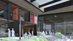
For example, during construction the team realised that they could streamline the installation of stairs against an existing brick wall in the museum’s foyer by changing them from concrete to steel, removing five months from the project’s critical path and accelerating the opening of the museum.
The precision of the scanned data was the key factor in the contractor’s decision to allow this change.
“Typical figures for a similar project, but without using reality computing, would have been in the order of 50 RFIs and 25 change orders, probably adding $100 or $150K more to the already $880K scope of work,” says Partridge.
In addition, just five or ten years ago, I would have suggested that the client carried at least a 20 percent contingency on the steel package to cover field rework on a project like this.
Without spending hundreds of thousands of dollars to hand measure the existing building, there was no other way to mitigate the risk of fitting a structural frame into the existing building.
Scanning and reality computing greatly reduces the cost of that capture and modelling effort, which in turn reduces the risk.”
Going forward
The UCAMA was on schedule to be enclosed in autumn 2014, with an opening of the initial gallery space planned the spring of 2015.
After this opening, work will continue on a second phase of the project, fitting out remaining portions of the building. As the project team finishes the phases, they plan to scan the entire project before closing up the walls (particularly the building systems and the structure) and give UCAMA an accurate as-built point cloud of the facility combined with the Revit-based as-built model and design documents.
“From an owner’s perspective, the only sources of truth are the scanned point clouds and the derivative model,” says Partridge.
“I believe that in 10 or 15 years, industry will be supplying owners building models and drawings to document what is in the building, along with point clouds to precisely locate the elements in the models and drawings.”
If you enjoyed this article, subscribe to AEC Magazine for FREE