Software is helping deliver beautiful structures that span huge distances with minimal materials. Peter Debney, application specialist at Oasys, shares some great examples in tension and compression
Apart from the weight, there is nothing lightweight about lightweight structures. With traditional structures, the loads are resisted by the stiffness in the beams, columns, and walls; with tension-only and compression-only structures, the overall form of the structure becomes critical. Get the form right and the structure can span huge distances with minimal material; get the form wrong and you are in trouble.
In fact, all structures are nonlinear; it’s just that the simpler linear analysis usually gives answers that are close enough for the majority of engineering design challenges; but new lightweight structures and materials call for a more thorough analysis.
So what makes nonlinear different to linear analysis? One of the most important things to remember is that while with linear analysis you establish equilibrium of the forces on the original geometry, with a nonlinear analysis you get equilibrium of the forces on the deflected shape. The problem is, you do not know what the deformation is until you have resolved the forces and you cannot resolve the forces until you know the deformation. All nonlinear analyses requires iteration. The faster the better.
Tension structures
Cables
While linear structures resist lateral loads with bending stiffness, light-weight nonlinear tensile structures have to deflect a long way until the forces are in balance.
A single loaded cable, describing a catenary (the curve that an idealised hanging chain or cable assumes under its own weight, familiar to us from suspension bridges) is stabilised out-of-plane by gravity and possibly additional factors such as a bridge deck. However, such structures are still vulnerable to sway, whether induced by wind or pedestrians. A solution to this problem (though not normally for bridges) is to have cables going in multiple directions, so sway in one direction is resisted by cables at other angles, giving what is called a cable net.
If such a cable net is horizontal and loaded it will deflect down with an essentially catenary shape, giving resistance to gravity loads, but there is still a problem: what about uplift forces on such a cable net when it is clad? Suction would be resisted purely by the self-weight of the structure, but that is potentially minimal with lightweight structures. The solution is to have the cables in one direction curved down to resist gravity loads, and those in the other direction curved upward to resist suction loads. This double-curved hyperbolic surface is characteristic of many cable nets and the shape naturally gives stiffness in all directions.
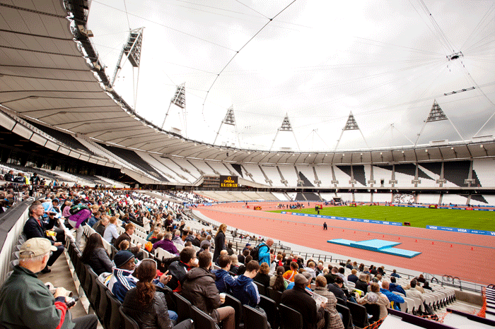
So what does such a double curved surface look like? An example is Expedition’s Velodrome for the London 2012 Olympics, famous for its ‘Pringle’ shaped roof.

Fabrics
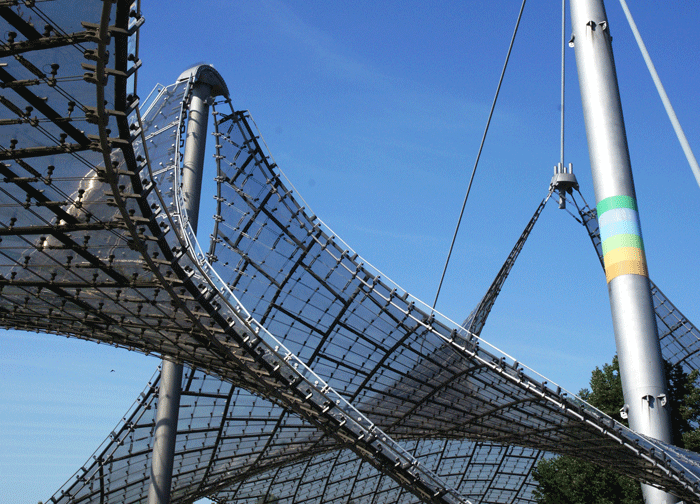
The modern science and engineering of fabric structures was pioneered by Frei Otto, with his roof to the Munich Olympic Games. Rejecting the heavy wartime architecture of Nazi Germany, Otto aspired to make modern architecture as light as possible, in both senses of the word: the Munich roof achieved this by using both a minimum of material and maximum glazing.
Fabrics are woven and this gives rise to warp-weft interaction, making them sensitive to the balance of pre-stresses in the two principle directions. The fabric will wrinkle as a whole if the pre-stress is much higher in one direction than the other. A correctly tensioned fabric will be smooth; unbalanced tensions will wrinkle the surface.
Fabrics require an edge support, which can either be solid, such as a beam, or flexible, such as a cable. With flexible edges, the cable’s curvature is dependent on the balance in the pre-stress between the cable and fabric and calculating this has quite an impact on the aesthetics and geometry of the fabric structure.
Foils
Foils, which are isotropic plastic sheets made from materials such as ETFE, have been used on iconic structures such as The Eden Project in Cornwall and the Beijing 2008 Olympics’ Water Cube.
Foils are generally used in inflated pillows, so each cladding panel is actually two or three separate layers supported by pressurised air. Wind loads on one surface are carried through the contained air to load the opposite face, so the whole remains in tension, plus the air can be heated to prevent snow loads. Unlike fabrics, foils have a good shear strength so have to yield under load to achieve their final form.
Like fabrics, form finding and the correct cutting patterns are critical.

Compression structures
Flying buttresses at Westminster Abbey
While tension-only structures deflect forces to balance the loads, compression-only structures, which can take the form of arches, shells, grid shells, and walls do not have this luxury as any movement increases the risk of buckling. This is a major risk for masonry structures as they have little or no bending capacity other than that provided by the compression thrust. While a masonry structure behaves linearly when the forces are low, it becomes nonlinear as soon as bending and buckling starts to open the joints.

Sagrada Familia
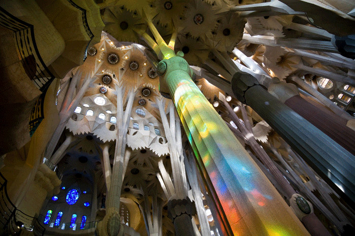
Exemplifying the potential for lightweight structures is Antoni Gaudi’s emblematic Sagrada Familia in Barcelona, due for completion in 2026 or 2028, more than 140 years after it was started.
While columns and walls in medieval cathedrals were braced with flying buttresses, the Sagrada Familia has angled columns so as to take the loads in direct compression. This removes the need for buttressing and the end result is something much more natural-looking. Gaudi used physical models to form find the structure; we can now use software such as Oasys GSA to achieve the same result.
Arup engineers are designing some of the remaining structures to withstand both gravity, wind, and seismic forces.
Tensegrity
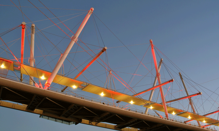
One progression of lightweight structural design is tensegrity, where elements are either in pure tension or compression, and ideally no two compression elements should be in contact. Tensegrity was a term coined by Buckminster Fuller and is described variously as “islands of compression in an ocean of tension” and “God’s geometry”. Brisbane’s Kurilpa, the world’s first bridge created using tensegrity, was designed by Arup engineers and called for purpose-written software that linked into Oasys GSA for the form finding, nonlinear static, and vibration analyses.

About the author
Peter Debney is a structural engineer with over 25 years experience in computing applications, in practice and in engineering software, BIM, analysis and design.
If you enjoyed this article, subscribe to AEC Magazine for FREE


