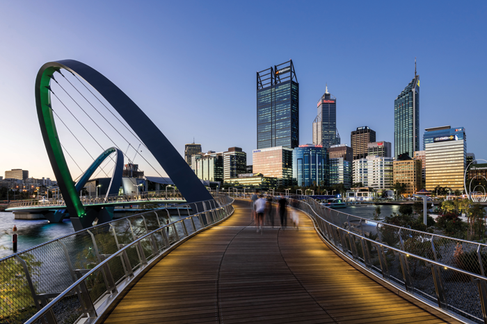
With its artful curves and breathtaking views, the Elizabeth Quay pedestrian bridge is a highlight of the Western Australian Government’s project to revitalise central Perth
The jewel in the crown of the Elizabeth Quay precinct in Perth, Australia is its graceful dualarched pedestrian and cyclist bridge. A striking engineering feat, the 22m-high cable-stayed bridge spans the inlet, visually linking city and water and offering impressive 360-degree views across the Swan River and the Perth Central Business District (CBD).
An artfully meandering structure, the 110m-long bridge allows for continuous movement around the quay, so that visitors can now walk, run, cycle or even segway across it as they explore the 2.7ha inlet, where a 1.5ha promenade features restaurants and bars soon to be jo ined by a vibrant mix of offices, apartments, hotels and retail outlets. According to those behind it, the AU $440m Elizabeth Quay project returns the city’s focus to the Swan River and provides a worldclass waterfront destination for Perth.
Meanwhile, the firm behind the bridge, Arup, recently took the prize for pedestrian bridges at The Structural Awards 2016, held at The Brewery venue in London. The judges were impressed by the contribution made by this elegant structure to the enhancement of central Perth. “Successfully overcoming a number of technical challenges, the bridge will serve as a landmark for the community,” they commented.
Design challenges
A bridge is, in essence, a very simple structure — but the design of the Elizabeth Quay pedestrian bridge, and the client’s aesthetic and functional briefs, presented three core challenges.
First, within its constrained location, the bridge design had to be simple, iconic and transparent. It needed to take into account the outstanding potential to frame exciting views of the city, the river and South Perth, as well as views from Kings Park.
Second, the bridge deck needed to be high enough for public ferries to pass safely underneath, in order to access the new terminal located within the quay. At the same time, it had to satisfy gradient requirements for universal accessibility.
Third, the bridge had to have a minimum clear width of 5m, to enable pedestrians and cyclists to use it easily and safely, so that movement around the quay was encouraged. It also needed to be a key destination in itself.
The concept design was driven by the designers’ desire to achieve a form for the bridge that respected the master plan of the quay, and used its location to advantage, with the goal of exceeding the client’s aesthetic and functional expectations. Parametric design tools were the key to the complex curves that responded to all three aspirations. The sinuous ‘S’ form of the 110m-long bridge deck has the necessary length required to clear the navigation channel, while providing dynamic and changing viewpoints for people using the bridge.
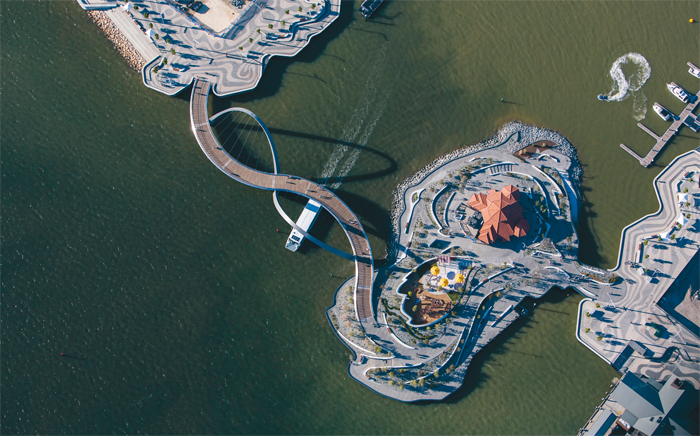
This form creates natural vantage points for locals and visitors, looking out to the Swan River and back towards the heart of Elizabeth Quay, with the Perth CBD as a backdrop. Day and night, it acts as a focal point, with integral feature lighting creating a relaxing and sophisticated ambience on the quay when night falls. The two 22m-high arches that support the deck lean away from each other, acting as complementary foils to the bridge deck form.
Combining architectural and artistic geometric concepts, Arup delivered a bridge structural deck that was only 250mm deep at the edges. This elegance is emblematic of the team’s ingenious, holistic approach to collaborative architectural and engineering design. Maintaining visual simplicity is at the core of the bridge’s design, despite the many structural complexities. There is clarity in both the architecture and structural engineering elements of the bridge, and where they have been pulled together, they have been kept as simple and as clean as possible – from the macro-scale of the cable alignments to the finer details, such as the shadow-line created by the deck drainage edge.
Digital workflows
The digital design workflow was a highly collaborative process that proved to be pivotal in the successful delivery of the project. The architect used Rhino and Grasshopper as parametric tools to converge quickly on the architecturally desired ‘S’-shaped bridge concept.
Preferred sculptural forms of the bridge were developed parametrically with the architect using Grasshopper, opening up the opportunity for Arup’s engineers to link into the architect’s parametric scripts to integrate the design workflow.
Working from the same shared Grasshopper canvas, the engineering team was able to generate analysis models to assess the structural performance of the bridge form as it developed in concept. 1D finite element models were parametrically generated directly from Grasshopper to GSA using Arup’s own Salamander plugin. These direct digital links provided the design team with the ability to optimise and rationalise the complex bridge form in a very short timeframe.
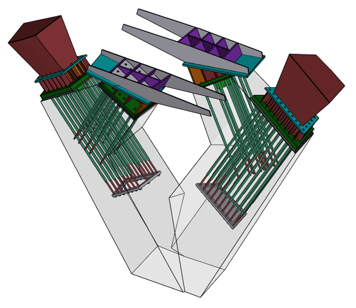
The engineers extended the architect’s initial Grasshopper scripts to generate all the internal steelwork necessary to describe the structure. This geometry was then referenced into Revit to populate the BIM model and produce the structural documentation. A fully detailed Strand7 analysis model consisting of 2D shell elements was also translated from the Grasshopper surface geometry which was used for final structural verification.
This ‘holistic workflow’ approach meant that direct relationships were made to the shared geometry between architect and engineer via their linked scripts. This association meant that architectural and structural refinements could occur in parallel, without losing element-to-element connectivity or resulting in the separation of modelling parts. In this way, time-consuming rework at each design update could be avoided. As an outcome of the digital workflow, complete coordination and alignment of design between architect and engineer was maintained throughout.
Parametric and analytic modelling
The plan geometry of the bridge was set out parametrically from a series of arcs, subdivided by equally spaced planes, perpendicularly aligned to their varying radii. Each of these planes was then set out vertically via an unrolled section taken through the bridge centreline. Onto each plane, a detail of the bridge cross-section was projected, and then lofted together from plane to plane. This in turn set out all the various 3D elements of the bridge: the structural section, fascia panels, timber decking, handrails and balustrade.
A typical Grasshopper workflow would be defined by numerical inputs, including sliders, formulae and graphs, linked by often restrictive and complex relationships, to drive the 3D geometry design. In turn, sections could be retrospectively cut from the baked geometry and transformed into drawings.
However, for the set-out modelling of the Elizabeth Quay pedestrian bridge, physically drawn inputs were used to drive the centre-line and cross-section model. This provided a shortcut for the parametric process where, too often, many rules can be forced upon the designer by a strict definition. Instead, the definition provided the conduit, using directly drawn 2D information, to create the 3D geometry. The 3D geometry could then be immediately updated, interrogated and assessed. Changes could be fed back rapidly by updating simple sections and detail drawings.
The use of Arup’s Salamander plug-in for Rhino and Grasshopper permitted instant generation of the structural analysis model. Analytical centreline geometry was directly obtained from the architect’s Grasshopper scripts, with the varying section profiles of the deck, piers and arches generated from parametric planes made at finite cuts appropriate to the level of analysis. Salamander components in Grasshopper were used to translate this information into 1D finite element model Oasys GSA.
The parametrically linked analysis model meant that changes to the bridge architecture could be implemented into the analytical model in real-time. This workflow led to direct savings for the client, through reduced steel tonnage, and indirectly, through avoiding additional items such as tuned-mass dampers.
Aesthetically, the depth of the bridge deck was reduced significantly through analysis modelling, which also exceeded the expectations of the clients, the artist and the architects who all wanted to achieve the thinnest possible deck profile. This approach justified a deck just 250mm deep along each side to span about 45m.
For final structural verification, a 2D plate finite element model was produced using Strand7. This model was also generated from the parametrically defined surface geometry in Grasshopper and read directly into Strand7 for auto-meshing. All plated steelwork, including the deck and arch profiles, the internal network of stiffener plates and connection at interfaces were meshed into the Strand7 model. The detailed model verified the final design and confirmed the overall bridge performance, stiffener buckling capacity, and ensuring that stress concentrations at critical connections were within acceptable limits.
If you enjoyed this article, subscribe to AEC Magazine for FREE